Voltage balance is probably the
single most important aspect of three-phase power quality.
Just a
slight voltage imbalance can damage a motor that is operating at
full capacity. Voltage balance is the Achilles heel of rotary and
static converters, and even utility three-phase service can be
unbalanced enough to harm three-phase equipment. The impact of this
problem is evident by the huge industry in manufacturing of devices
that monitor phase balance to protect motors.
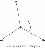
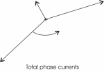
To demonstrate the impact of
voltage balance on a three-phase motor, measurements were taken on a
7.5 Hp rotary converter in an actual machine shop installation. The
recorded line-to-line voltages were 252 V, 244.2 V and 280.5 V,
which is about a 12% imbalance in the voltages. To understand how
voltage imbalance will effect a motor it is useful to first
transform these line-to-line voltages into their equivalent
line-to-neutral voltages, which are shown in figure 3 below. These
voltages are shown in what is called a phasor diagram. The
magnitude of each voltage is proportional to the length of the arrow
or vector and the relative phase angle of each voltage is
proportional to the angle between any two arrows. The L1-L2 voltage
has been arbitrarily drawn with an absolute angle of zero degrees.
If one imagines that these vectors are spinning around the center
point clockwise at a rate of 60 times per second, then the value of
a voltage at any particular instant in time would be the projected
length of its vector onto the horizontal axis. This set of vectors,
which represent unbalanced voltages, rotating clockwise, can be
further separated into two balanced sets of vectors, one rotating
counterclockwise and called the positive-sequence voltages, and one
rotating clockwise and called the negative-sequence voltages.
These are also shown in figure 1 below.
FIGURE 1

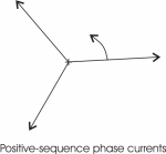
An induction motor responds quite
differently to the positive-sequence voltages as compared to the
negative sequence voltages. The positive-sequence voltages are
rotating at 60 Hz (3600 cycles/min) and if we take the example of a
2-pole motor, the rotor is spinning at about 3450 rpm. The slip
speed between the field created by the positive-sequence voltages
and the actual rotor velocity is low and the inductance seen by
these voltages is relatively large.
If we take
the example of a 7.5 Hp 240 V motor, the no-load running current is
about 14 A. The
phase-to-neutral voltage is 240/(3)1/2=139 V, and the
phase-to-neutral inductance is: L=139/(377*14)=26mH (1 mH=1
Henry/1000, a Henry being the basic unit of inductance). The
negative-sequence voltages are rotating in the opposite direction to
the rotor velocity and the slip is almost twice the rotor velocity.
This sequence of voltages sees an inductance nearly equal to that
which would be measured if the rotor were locked in position. The
locked-rotor inductance is about one sixth of the normal running
inductance or about 4.4 mH for a 7.5 Hp motor. The figure below
shows the individual positive and negative sequence currents and the
combined current for the voltages shown above.
|
FIGURE 2
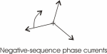
Notice that while the voltages were
only 12% out of balance, the currents differ by almost a factor of
three. Since the negative sequence voltages feed into an inductance
which is one sixth of the inductance seen by the positive-sequence
voltages, a rather modest imbalance in the voltages produces a
totally unacceptable imbalance in the currents.
In this example, the
lead to the motor carrying the smallest current could be totally
disconnected and it would not significantly change the performance
of the motor.
If a single motor is always run at
a constant load, and the rotary phase converter and its associated
capacitor bank are carefully adjusted, then it is possible to
achieve better than a 12% voltage imbalance as discussed in the
example above and get acceptable operation of the motor. The
procedure would involve setting up the system of phase converter,
motor and load; then measuring the generated voltages and the
currents in each motor phase. If the current balance were
unacceptable, then capacitors would need to be either added to, or
taken out of the capacitor bank until the currents were balanced.
In some cases, it might be necessary to switch to a different size
phase converter to get the system balanced.

If the motor were required to
operate over a wide range of load conditions, or if several motors
were powered using the same phase converter, it would be nearly
impossible to get good voltage balance over the whole range of
operation. If none of the motors were run at their full capacity,
the job of getting everything to work properly would be easier. If
the motor(s) were run at their full capacity for extended periods,
such as in pumping applications, they would not tolerate voltage
imbalance.
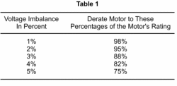
In summary, phase imbalance
adversely impacts both the performance and the life of a motor. Even modest voltage imbalance between the phases will require a
motor to be de-rated as indicated in Table 1. Phase
imbalance will significantly reduce the life of motors that have a
high duty cycle and operate at their maximum rated capacity.
 |
|