Electric Power
Distribution
The backbone of every modern
electric power distribution system is a three-phase alternating
current (AC) transmission line. It consists of three primary
current-carrying wires sometimes referred to as L1, L2, and L3 and
in some cases a fourth wire called the neutral conductor.
Single-phase distribution systems are also common because
single-phase transmission lines costs significantly less than
three-phase lines. They consist of one high-voltage line and a
neutral. Most residential and rural areas are supplied with
single-phase service.
|
Three-phase power cannot be supplied from single-phase service
unless a phase converter is used.
Single-phase power is a single
voltage that alternates between a positive voltage and a negative
voltage for a specific number of times per second (in the U.S., 60
times per second or 60 Hz). Three-phase power is three distinct AC
voltages, each shifted in time 120 degrees relative to one another
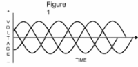
as depicted in figure 1.
The wave forms shown in figure 1
can be calculated using the sine function in trigonometry and are
called sine waves. Notice that the voltage between L2 and neutral
(L2-N) is delayed by 1/3 of a cycle from the L1-N voltage, and that
the L3-N voltage is displaced 1/3 of a cycle from the L2-N voltage.
A complete cycle of the one of the wave forms corresponds to one
complete rotation around a
|
circle or 360
degrees. The phase delay in the L2 and L3 voltages is often
referred to as 1/3 times 360 degrees or 120 degrees for L2 and 240
degrees for the L3 voltage.
Customers are supplied with
electricity from the distribution system by placing transformers on
the high voltage distribution system to reduce voltage to a level
compatible with electric devices, for example, 240 volts.
Three-phase service requires three transformers compared to one for
single-phase service, and requires different metering equipment as
well. Because of this, three-phase service costs more to install,
so utilities usually prefer to install single-phase service unless
there is a specific demand for three-phase power at the site.
 |
|