Power Factor Defined
Power factor describes the relationship between real
and apparent power of alternating current (AC) power systems.
In an AC power system, current may flow into and back out of a load
without delivering any energy. This reactive current gives
rise to “apparent power” which is larger than the actual power
consumed.
Power factor is expressed as the ratio of the actual
power to the apparent power.
A power factor of 1.0, or “unity” is desirable because
it means that all the power delivered to the load is “real power”
and there is no reactive current component to the load. As the
reactive current and apparent power increase, power factor is
expressed as a smaller decimal.
The Impact of Power Factor
A poor power factor is undesirable because even
though the power is “apparent”, the current is real and the utility
has to generate that current and allow capacity in its lines to
carry it. The typical meter does not measure apparent power which
is why the utility may choose to charge a customer a penalty for
poor power factor. And even if the utility doesn’t charge for it,
poor power factor can cost a customer by wasting energy through I2R
heat losses and overloading the capacity of wires and breakers.
Phase Converters and Power Factor
Rotary phase converters employ a three-phase AC
induction motor, and causes a poor “lagging” power factor,
therefore, this means that as the current and voltage of the AC
power alternate between positive and negative, the peak current lags
the peak voltage in time. Inductive loads can cause a poor "lagging"
power factor, as well. Most often a phase converter is
powering inductive loads which also have a poor lagging power
factor. When combined with the poor power factor of the rotary
converter, the
power factor on the utility line side of the converter becomes very
low, often as low as 0.65. This means that nearly 1/3 of the current
flowing in and out of the system is not delivering any real power.
This reactive current can overload the wiring and circuit breakers and if the
converter and load are large enough it can overload the step down
transformer at the utility service drop and cause the voltage to sag
on the utility system.
VFDs and Power Factor
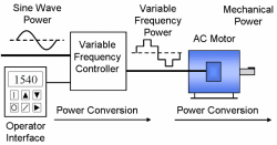
VFDs are sometimes used as phase converters and can
create problems related to power factor. Unlike rotary phase
converters where the peak current lags the peak voltage, VFDs will
draw current that is in time with the voltage. The problem
arises from the current being drawn in a dramatic spike instead of a
smooth sine wave.
 |
This sudden and dramatic current causes harmonic
distortion to be introduced into the current. This can create
problems for other electrical equipment on the service, and if the VFD and load are large enough it can overload the step down
transformer at the utility service drop. The distorted nature of
the input current is due to the type of rectifier used on VFDs.
Diodes or SCRs are used to “rectify” the incoming AC power, which
converts the power to DC by charging capacitors on a DC bus. VFD
manufacturers will sometimes specify the power factor of their
drives as unity “displacement” power factor. This is not the same
as true unity power factor and the damaging harmonics will still be
present in the input current.
The addition of input line reactors, which are
inductive filters, to the line side of the VFD will
mitigate most of the harmonics and are offered as an option by most
drive manufacturers.
Digital Phase Converters and Power Factor
Genuine digital phase converters will operate at true
unity power factor under all load conditions with almost no
distortion of the input current. This makes them a very efficient,
utility-friendly phase converter. Like a VFD, a digital phase
converter rectifies incoming AC power to DC, but the rectifier is of
a completely different design. It utilizes
IGBTs (insulated gate bipolar transistors)
in series with an inductor on the input rectifier module. Software
in the converter’s microprocessor controls the IGBT so that the
current is drawn in a sinusoidal fashion. This process is known as
electronic power factor correction. So rather than compound the
power factor of inductive loads like a rotary converter, a digital
phase converter actually corrects the power factor of the load,
supplying the reactive current the load needs while the utility sees
a load that operates at unity power factor. The electronic power
factor correction can also reduce the impact of
motor starting currents,
allowing larger motors to be started across-the-line without causing
line disturbances on the single-phase line.
A phase converter that operates at
true unity power factor is efficient and utility-friendly. Compared
to other converters, it can operate the same load on a smaller
utility step-down transformer. It will not be as likely to overload
wiring and circuit breakers and wastes less energy.
More information on Power Factor.
|
|